knowledge starts by defining the user requirements to meet needs
Programmable Logic Controllers
Equity and Project Templates
Failure Mode Effect Analysis and the cycle of defining User Requirements
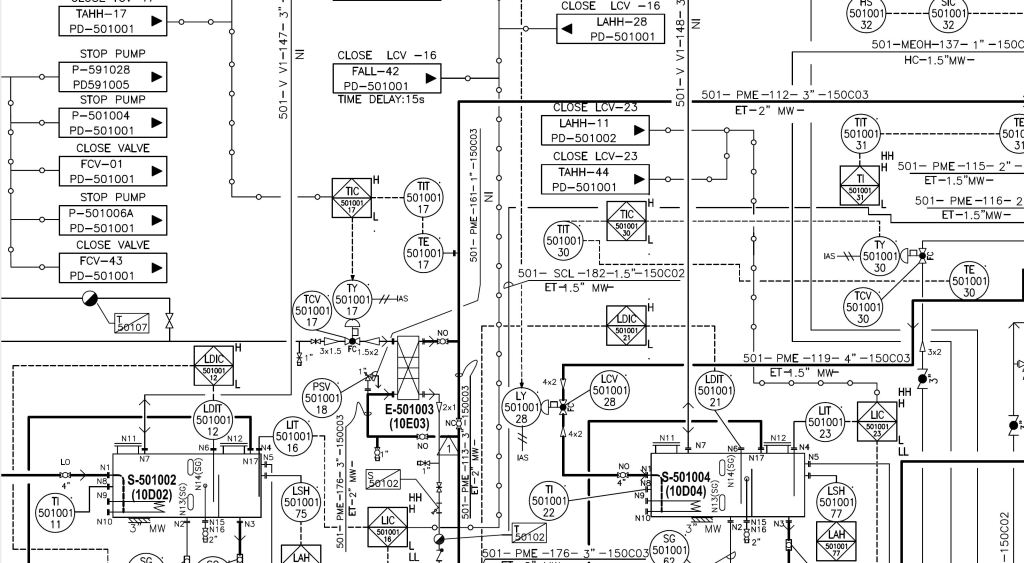
Piping and Instrumentation Diagrams or Process and Instrumentation Diagrams
Engineering Services
RFQ to Sales@layer1holdings.com
Required Specification make engineering easier, the more clear the specifications the less degrees of freedom and ambiguity.
Failure Mode Error Analysis (FMEA , DFMEA, PFMEA, BFMEA)
what are the failure modes, what are the consequences of those failure modes, the occurrence rate of the failure mode and the detection that when it fails you will know it failed.
Do this for every Process you want to document risk. This FMEA should help you derive your user required specifications.

Control Plans or Critical Control Points Should have their needs specified from the FMEA
Factory Acceptance Testing can be documented in an FMEA
Root Cause Analysis will be a feedback to a FMEA both in failure modes and frequency feedback
Piping and Instrumentation Diagrams (P&IDs) will guide the FMEA by providing a process Map
Alarm Rationalization should come from the Failure Mode Effect Analysis (FMEA )
as a risk reduction (no task that requires human intervention can be reduced by a whole amount
Single Line Diagrams and Programmable Logic Controller Wire Diagrams
Validation Program
Failure Mode Effect Analysis down to every item on the bill of materials provides testing requirements to meet user requirements
Equipment Qualification
SOP Authorizing
Protocol/Report Template Drafting
Bifold Level Training
Tooling Qualification
Computer System Validation
Non-Product Software Validation
Cleaning Validation
Facilities/Utilities Qualification
Test Method Validation
Validation Master Plan
Site Master Validation Plan
Master Validation Plan
